CNC Pipe Threading Machine
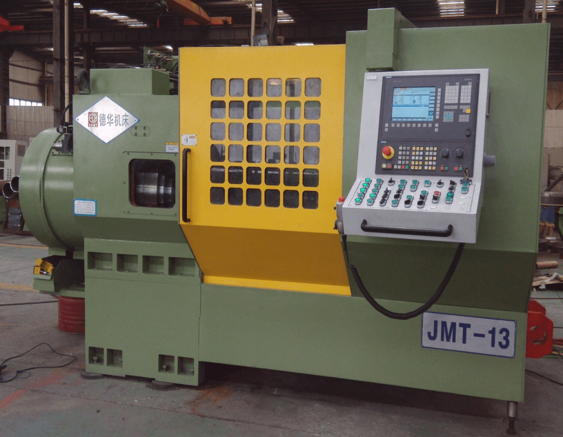
Our CNC pipe threading machine is engineered for precision and efficiency, making it the ideal solution for OCTG pipe threading operations. This CNC pipe threading machine combines advanced technology with robust design to deliver superior performance in the steel pipe industry.
Moreover, the machine adopts a cutting approach where the pipe rotates while the tool moves linearly, ensuring smooth and accurate threading. It performs multiple tasks in one setup, including external turning, end-face finishing, chamfering, thread cutting, deburring, and sealing surface machining. As a result, manufacturers achieve higher productivity and consistent quality.
In addition to API 5CT and 5B standard threads, this OCTG pipe threading machine can process various special thread profiles, meeting diverse customer requirements. Furthermore, its multi-tool configuration significantly reduces cycle time, which translates into improved operational efficiency.
To enhance flexibility, the CNC pipe threading lathe can be equipped with leading CNC systems such as FANUC or Siemens. Therefore, operators benefit from intuitive controls and stable performance, even in demanding environments. This steel pipe threading lathe is not just a machine—it is a comprehensive solution for modern pipe processing.
Ultimately, investing in a CNC pipe threading machine means embracing automation, precision, and reliability. Consequently, your production line will experience reduced downtime, optimized throughput, and superior threading accuracy.
Main Features of the CNC Pipe Threading Machine
Our CNC pipe threading machine is designed for precision and efficiency, making it the ideal solution for high-performance pipe processing. This CNC pipe threading machine integrates advanced global design concepts with superior rigidity and accuracy, ensuring exceptional results for OCTG and steel pipe threading applications
01. Innovative Design Concep
The machine features advanced design inspired by world-class products, delivering exceptional precision and efficiency for superior performance in demanding environments.
02. High Rigidity Structure
This lathe features a 45° slant bed, large-diameter spindle, and tapered roller bearings with high load capacity, ensuring stability during heavy-duty cutting. Users gain consistent accuracy and extended machine life.
03. Superior Precision
Equipped with precision bearings, advanced feed components, and a rigid box-type base, the machine delivers superior accuracy, stable positioning, and long-term reliability—surpassing domestic standards and rivaling imported models.
04. Structural Highlights
The machine features dual hydraulic chucks for secure clamping, a five-axis dual-channel system for efficient complex machining, and three tool posts enabling multi-tool operations, significantly improving productivity and reducing cycle time.
05. Transmission System
The main drive uses a spindle servo motor with synchronous belt and gear transmission. The first channel features a servo motor, ball screw, and steel-inlaid guideways, while the second channel combines a servo motor, ball screw, and rolling guideways.
06.Efficiency and Performance
By optimizing rigidity, strength, wear resistance, and vibration damping, and applying a multi-tooth comb cutter process, this OCTG pipe threading machine ensures powerful, efficient threading. It supports low-speed, high-torque cutting, high metal removal rates, and fast cycles for reliable, productive performance.
07.High Reliability and Easy Maintenance
Critical components, including bearings, hydraulic systems, lubrication, cooling, belts, electrical parts, and ball screws, are sourced from leading global brands. This ensures stable operation, enhances reliability, and significantly reduces maintenance costs for the CNC pipe threading lathe.
08.Advanced Control and User-Friendly Interface
The machine is equipped with Siemens 840D or FANUC CNC systems, providing intuitive controls and an ergonomic interface. Advanced software functions further enhance the operator experience, simplifying complex operations and improving overall efficiency and productivity.
Techinical Specification
Performance specification
| Item | Unit | Specification |
|---|---|---|
| Processed Tube Dia | mm | 1.9″-4 1/2″ |
| Processed Tube Length | mm | 4620mm-12500 mm |
Spindle System Specification
| Items | Unit | Specification |
|---|---|---|
| Spindle Through Hole Dia | mm | 145 |
| Spindle Speed | Rpm | 300-1000 |
| Spindle Motor | KW | 110 |
| Height of spindle center from ground | mm | 1200 |
Feeding System of the pipe threading Machine
| Items | Unit | Specification |
|---|---|---|
| X1/Y1/Z1 axis Travel | mm | 110/110/550 |
| X2/Z2 Axis Travel | mm | 140/700 |
| X1/Y1/Z1 axis Fast Speed | mm/min | 15 |
| X2/Z2 Axis Fast Speed | mm/min | 20 |
hydraulic turret System
| Items | Unit | Specification |
|---|---|---|
| Positions | Station | 5-6 |
| Drive Pattern | Servo motor or hydraulic motor drive rotation |
Hydraulic System
| Item | Unit | Specification |
|---|---|---|
| Hydraulic Pump Motor | Kw | 5.5 |
| Pump Flow | L/min | 40 |
| Machine Work Pressure | Bar | 70 |
| Hydraulic Oil tank Capacity | L | 200 |
| Accumulator capacity | L | 20 L ( 35bar ) |
Spindle Cooling and Lubricating System
| Item | Unit | Specification |
|---|---|---|
| Oil Pump Motor Power | HP | 3 |
| Oil Pump Flow | L/Min | 60 |
| Working Pressure | bar | 3-5 Bar |
| Oil Tank Capacity | L | 160 |
Centralized Lubricating System
| Item | Unit | Specification |
|---|---|---|
| Oil Pump Motor Power | W | 20 |
| Oil Pump Flow | L/Min | 0.15L /Min |
| Working Pressure | Bar | 20 |
| Oil Tank Capacity | L | 4 |
Emulsion cooling system
| Item | Unit | Specification |
|---|---|---|
| Emulsion Pump Motor | kw | 4 |
| Emulsion Pump Flow | L /Min | 100 |
| Working Pressure | Bar | 25 |
| Water Tank Capacity | L | 1200 |
Working Accuracy
| Item | Unit | Specification |
|---|---|---|
| Position Accuracy (x/y/z) | mm | 0.012 / 0.012 /0.020 |
| Repeated Position Accuracy (X/Y/Z ) | mm | 0.008 / 0.008 /0.010 |
| Backlash (X1/Y1/Z1) | mm | 0.02 |
| Workpiece circular run-out error | mm | +- 0.01 mm /200mm |
| Surface roughness of workpiece | – | Not Less Than Ra1.6 |
Control System
| Item | Unit | Specification |
|---|---|---|
| NC System | – | Siemens 840 Ds1 |
Performance specification
| Item | Unit | Specification |
|---|---|---|
| Processed Tube Dia | mm | 2 3/8″-7′ |
| Processed Tube Length | mm | 4620mm-12500 mm |
Spindle System Specification
| Items | Unit | Specification |
|---|---|---|
| Spindle Through Hole Dia | mm | 165 |
| Spindle Speed | Rpm | 150-1000 |
| Spindle Motor | KW | 160 |
| Height of spindle center from ground | mm | 1200 |
Feeding System of the pipe threading Machine
| Items | Unit | Specification |
|---|---|---|
| X1/Y1/Z1 axis Travel | mm | 110/110/550 |
| X2/Z2 Axis Travel | mm | 140/700 |
| X1/Y1/Z1 axis Fast Speed | mm/min | 15 |
| X2/Z2 Axis Fast Speed | mm/min | 20 |
hydraulic turret System
| Items | Unit | Specification |
|---|---|---|
| Positions | Station | 5-6 |
| Drive Pattern | Servo motor or hydraulic motor drive rotation |
Hydraulic System
| Item | Unit | Specification |
|---|---|---|
| Hydraulic Pump Motor | Kw | 5.5 |
| Pump Flow | L/min | 40 |
| Machine Work Pressure | Bar | 70 |
| Hydraulic Oil tank Capacity | L | 200 |
| Accumulator capacity | L | 20 L ( 35bar ) |
Spindle Cooling and Lubricating System
| Item | Unit | Specification |
|---|---|---|
| Oil Pump Motor Power | HP | 3 |
| Oil Pump Flow | L/Min | 60 |
| Working Pressure | bar | 3-5 Bar |
| Oil Tank Capacity | L | 160 |
Centralized Lubricating System
| Item | Unit | Specification |
|---|---|---|
| Oil Pump Motor Power | W | 20 |
| Oil Pump Flow | L/Min | 0.15L /Min |
| Working Pressure | Bar | 20 |
| Oil Tank Capacity | L | 4 |
Emulsion cooling system
| Item | Unit | Specification |
|---|---|---|
| Emulsion Pump Motor | kw | 4 |
| Emulsion Pump Flow | L /Min | 100 |
| Working Pressure | Bar | 25 |
| Water Tank Capacity | L | 1200 |
Working Accuracy
| Item | Unit | Specification |
|---|---|---|
| Position Accuracy (x/y/z) | mm | 0.012 / 0.012 /0.020 |
| Repeated Position Accuracy (X/Y/Z ) | mm | 0.008 / 0.008 /0.010 |
| Backlash (X1/Y1/Z1) | mm | 0.02 |
| Workpiece circular run-out error | mm | +- 0.01 mm /200mm |
| Surface roughness of workpiece | – | Not Less Than Ra1.6 |
Control System
| Item | Unit | Specification |
|---|---|---|
| NC System | – | Siemens 840 Ds1 |
Performance specification
| Item | Unit | Specification |
|---|---|---|
| Processed Tube Dia | Inch | 4 1/2”-9 5/8” |
| Processed Tube Length | mm | 4620mm-12500 mm |
Spindle System Specification
| Items | Unit | Specification |
|---|---|---|
| Spindle Through Hole Dia | mm | 280 |
| Spindle Speed | Rpm | 800 |
| Spindle Motor | KW | 160 |
| Height of spindle center from ground | mm | 1200 |
Feeding System of the pipe threading Machine
| Items | Unit | Specification |
|---|---|---|
| X1/Y1/Z1 axis Travel | mm | 140/140/550 |
| X2/Z2 Axis Travel | mm | 140/700 |
| X1/Y1/Z1 axis Fast Speed | mm/min | 15/15/15 |
| X2/Z2 Axis Fast Speed | mm/min | 20/20 |
hydraulic turret System
| Items | Unit | Specification |
|---|---|---|
| Positions | Station | 5-6 |
| Drive Pattern | Servo motor or hydraulic motor drive rotation |
Hydraulic System
| Item | Unit | Specification |
|---|---|---|
| Hydraulic Pump Motor | Kw | 5.5 |
| Pump Flow | L/min | 40 |
| Machine Work Pressure | Bar | 70 |
| Hydraulic Oil tank Capacity | L | 200 |
| Accumulator capacity | L | 20 L ( 35bar ) |
Spindle Cooling and Lubricating System
| Item | Unit | Specification |
|---|---|---|
| Oil Pump Motor Power | HP | 3 |
| Oil Pump Flow | L/Min | 60 |
| Working Pressure | bar | 3-5 Bar |
| Oil Tank Capacity | L | 160 |
Centralized Lubricating System
| Item | Unit | Specification |
|---|---|---|
| Oil Pump Motor Power | W | 20 |
| Oil Pump Flow | L/Min | 0.15L /Min |
| Working Pressure | Bar | 20 |
| Oil Tank Capacity | L | 4 |
Emulsion cooling system
| Item | Unit | Specification |
|---|---|---|
| Emulsion Pump Motor | kw | 4 |
| Emulsion Pump Flow | L /Min | 100 |
| Working Pressure | Bar | 25 |
| Water Tank Capacity | L | 1200 |
Working Accuracy
| Item | Unit | Specification |
|---|---|---|
| Position Accuracy (x/y/z) | mm | 0.012 / 0.012 /0.020 |
| Repeated Position Accuracy (X/Y/Z ) | mm | 0.008 / 0.008 /0.010 |
| Backlash (X1/Y1/Z1) | mm | 0.02 |
| Workpiece circular run-out error | mm | +- 0.01 mm /200mm |
| Surface roughness of workpiece | – | Not Less Than Ra1.6 |
Control System
| Item | Unit | Specification |
|---|---|---|
| NC System | – | Siemens 840 Ds1 |
Performance specification
| Item | Unit | Specification |
|---|---|---|
| Processed Tube Dia | mm | 4 1/2“-13 3/8” |
| Processed Tube Length | mm | 4620mm-12500 mm |
Spindle System Specification
| Items | Unit | Specification |
|---|---|---|
| Spindle Through Hole Dia | mm | 380 |
| Spindle Speed | Rpm | 50-400 |
| Spindle Motor | KW | 160 |
| Height of spindle center from ground | mm | 1200 |
Feeding System of the pipe threading Machine
| Items | Unit | Specification |
|---|---|---|
| X1/Y1/Z1 axis Travel | mm | 160/160/550 |
| X2/Z2 Axis Travel | mm | 140/700 |
| X1/Y1/Z1 axis Fast Speed | mm/min | 15 |
| X2/Z2 Axis Fast Speed | mm/min | 20 |
hydraulic turret System
| Items | Unit | Specification |
|---|---|---|
| Positions | Station | 5-6 |
| Drive Pattern | Servo motor or hydraulic motor drive rotation |
Hydraulic System
| Item | Unit | Specification |
|---|---|---|
| Hydraulic Pump Motor | Kw | 5.5 |
| Pump Flow | L/min | 40 |
| Machine Work Pressure | Bar | 70 |
| Hydraulic Oil tank Capacity | L | 200 |
| Accumulator capacity | L | 20 L ( 35bar ) |
Spindle Cooling and Lubricating System
| Item | Unit | Specification |
|---|---|---|
| Oil Pump Motor Power | HP | 3 |
| Oil Pump Flow | L/Min | 60 |
| Working Pressure | bar | 3-5 Bar |
| Oil Tank Capacity | L | 160 |
Centralized Lubricating System
| Item | Unit | Specification |
|---|---|---|
| Oil Pump Motor Power | W | 20 |
| Oil Pump Flow | L/Min | 0.15L /Min |
| Working Pressure | Bar | 20 |
| Oil Tank Capacity | L | 4 |
Emulsion cooling system
| Item | Unit | Specification |
|---|---|---|
| Emulsion Pump Motor | kw | 4 |
| Emulsion Pump Flow | L /Min | 100 |
| Working Pressure | Bar | 25 |
| Water Tank Capacity | L | 1200 |
Working Accuracy
| Item | Unit | Specification |
|---|---|---|
| Position Accuracy (x/y/z) | mm | 0.012 / 0.012 /0.020 |
| Repeated Position Accuracy (X/Y/Z ) | mm | 0.008 / 0.008 /0.010 |
| Backlash (X1/Y1/Z1) | mm | 0.02 |
| Workpiece circular run-out error | mm | +- 0.01 mm /200mm |
| Surface roughness of workpiece | – | Not Less Than Ra1.6 |
Control System
| Item | Unit | Specification |
|---|---|---|
| NC System | – | Siemens 840 Ds1 |
Performance specification
| Item | Unit | Specification |
|---|---|---|
| Processed Tube Dia | Inch | 9 5/8“ -20” |
| Processed Tube Length | mm | 4620mm-12500 mm |
Spindle System Specification
| Items | Unit | Specification |
|---|---|---|
| Spindle Through Hole Dia | mm | 640 |
| Spindle Speed | Rpm | 50-400 |
| Spindle Motor | KW | 190 |
| Height of spindle center from ground | mm | 1290 |
Feeding System of the pipe threading Machine
| Items | Unit | Specification |
|---|---|---|
| X1/Y1/Z1 axis Travel | mm | 400/600 |
| X2/Z2 Axis Travel | mm | / |
| X1/Y1/Z1 axis Fast Speed | mm/min | 15/15/15 |
| X2/Z2 Axis Fast Speed | mm/min | / |
hydraulic turret System
| Items | Unit | Specification |
|---|---|---|
| Positions | Station | 5-6 |
| Drive Pattern | Servo motor or hydraulic motor drive rotation |
Hydraulic System
| Item | Unit | Specification |
|---|---|---|
| Hydraulic Pump Motor | Kw | 5.5 |
| Pump Flow | L/min | 40 |
| Machine Work Pressure | Bar | 70 |
| Hydraulic Oil tank Capacity | L | 200 |
| Accumulator capacity | L | 20 L ( 35bar ) |
Spindle Cooling and Lubricating System
| Item | Unit | Specification |
|---|---|---|
| Oil Pump Motor Power | HP | 3 |
| Oil Pump Flow | L/Min | 60 |
| Working Pressure | bar | 3-5 Bar |
| Oil Tank Capacity | L | 160 |
Centralized Lubricating System
| Item | Unit | Specification |
|---|---|---|
| Oil Pump Motor Power | W | 20 |
| Oil Pump Flow | L/Min | 0.15L /Min |
| Working Pressure | Bar | 20 |
| Oil Tank Capacity | L | 4 |
Emulsion cooling system
| Item | Unit | Specification |
|---|---|---|
| Emulsion Pump Motor | kw | 4 |
| Emulsion Pump Flow | L /Min | 100 |
| Working Pressure | Bar | 25 |
| Water Tank Capacity | L | 1200 |
Working Accuracy
| Item | Unit | Specification |
|---|---|---|
| Position Accuracy (x/y/z) | mm | 0.012 / 0.012 /0.020 |
| Repeated Position Accuracy (X/Y/Z ) | mm | 0.008 / 0.008 /0.010 |
| Backlash (X1/Y1/Z1) | mm | 0.02 |
| Workpiece circular run-out error | mm | +- 0.01 mm /200mm |
| Surface roughness of workpiece | – | Not Less Than Ra1.6 |
Control System
| Item | Unit | Specification |
|---|---|---|
| NC System | – | Siemens 840 Ds1 |
The Main Parts of the CNC Pipe Threading Machine
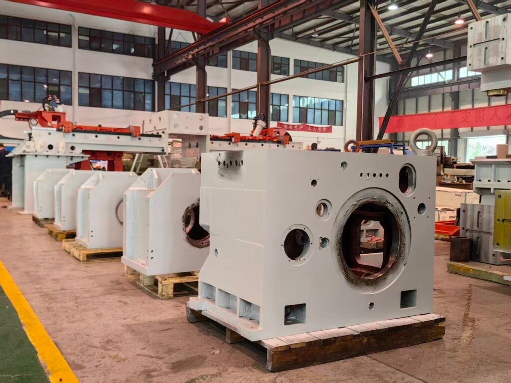
Our CNC pipe threading machine is engineered for precision, strength, and durability. The main body components are cast from high-strength, stress-relieved iron using resin sand molding, leveraging cast iron’s vibration-damping properties for lasting accuracy. Advanced finite element analysis optimizes the ribbed box-type framework, ensuring exceptional resistance to vibration, bending, and torsion under heavy cutting. Auxiliary parts use welded steel plates, treated and heat-processed to eliminate residual stress, delivering superior rigidity. Combined with precision machining, this design guarantees stability and reliability. Built for demanding OCTG and steel pipe threading applications, the machine offers outstanding accuracy, strength, and long-term performance.
01. Spindle Box /Main Bed
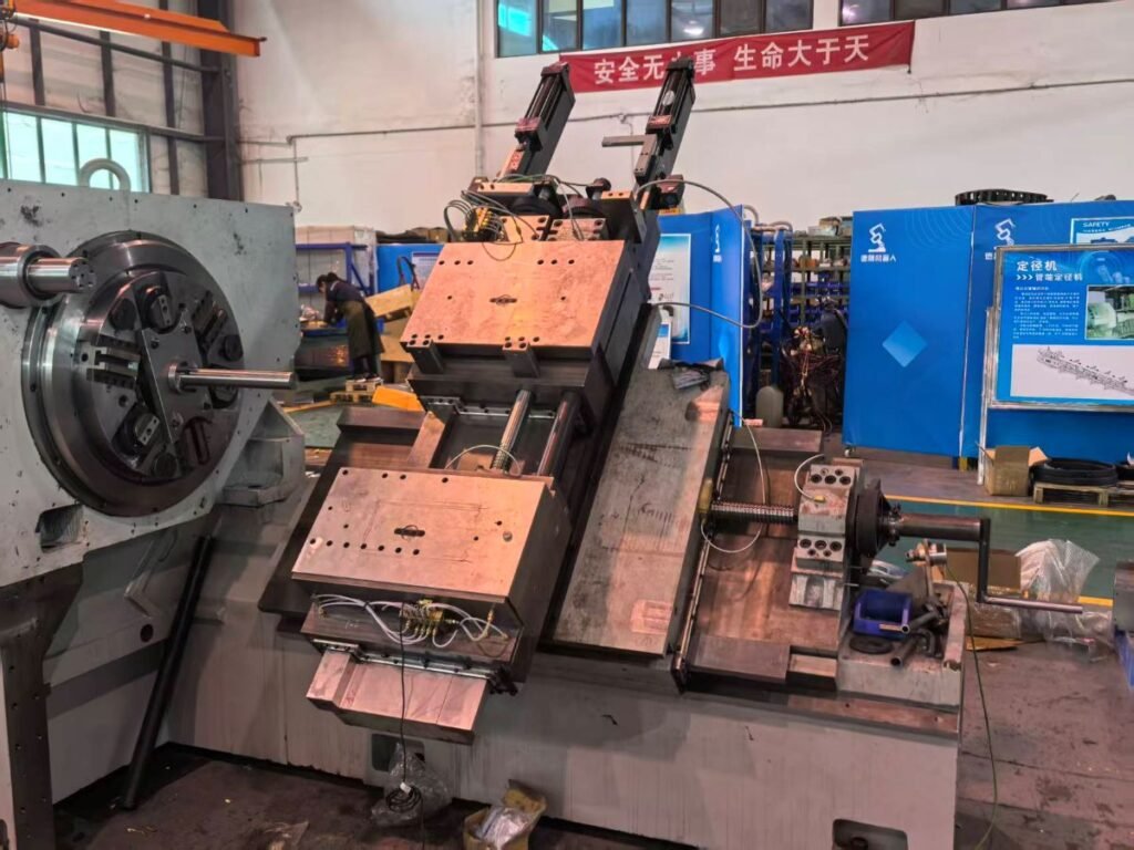
The spindle box is cast from high-performance iron, stress-relieved twice, and reinforced with dense ribbing for vibration resistance. Its large through-hole spindle uses imported tapered roller bearings, hydraulic cooling, and lubrication for rigidity and accuracy. The bed features a 45° slant guideway for optimal force distribution, spacious chip removal, and a closed-frame ribbed structure to resist bending and torsion. Cast from high-grade iron and treated for stress relief, it ensures cutting rigidity, machining precision, and long-term stability—ideal for heavy-duty pipe threading operations.
02. Feeding Carrige and Silde System
The CNC pipe threading machine uses hardened inlaid steel guideways with hardness above 60 HRC for superior wear resistance and long-term accuracy. Injection-molded sliding surfaces reduce friction and enhance rigidity, ensuring smooth low-speed, heavy-duty cutting. Hydraulic balancing cylinders support slides, reducing drive load and improving stability. This design delivers steady feed motion, high precision, and extended service life—ideal for demanding OCTG and steel pipe threading applications.
03. 5-Axis Feed System of the Channel 1ST
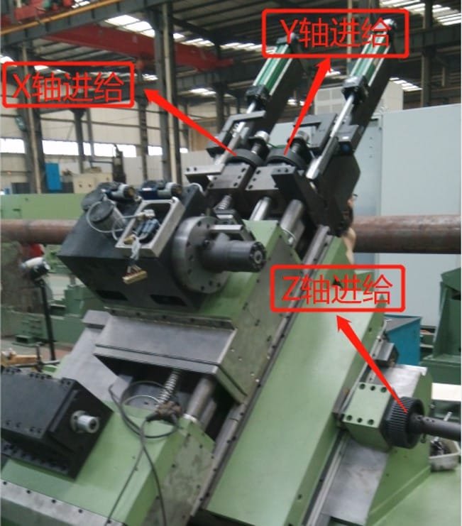
The three-axis feed system in Channel 1 uses imported INA ZARN heavy-duty needle-thrust cylindrical roller bearings to support each feed screw, providing high precision, rigidity, and load capacity. Grease lubrication ensures durability. The ball screw and feed motor are connected via a timing-belt reduction drive, increasing feed thrust compared to direct drive. A high-precision absolute encoder mounted at the ball screw end delivers real-time position feedback to the CNC, enabling full closed-loop control. This configuration ensures superior positioning accuracy and stable feed performance, making it ideal for demanding machining tasks. It is supplied as standard for Channel 1.

04. 5-Axis Feed System Channel 2nd
The CNC pipe threading machine incorporates a two-axis auxiliary feed system with longitudinal (Z2) and transverse (X2) axes mounted on a beam above the headstock. Both axes use servo motors, precision ball screws, and linear guideways for smooth, stable motion. Z2 is installed on X2 for structural support. Positioning data from both axes is transmitted to the CNC via servo encoders, enabling closed-loop feedback. This design ensures accuracy, reliability, and efficiency for demanding OCTG pipe threading operations.
05. Conformator System
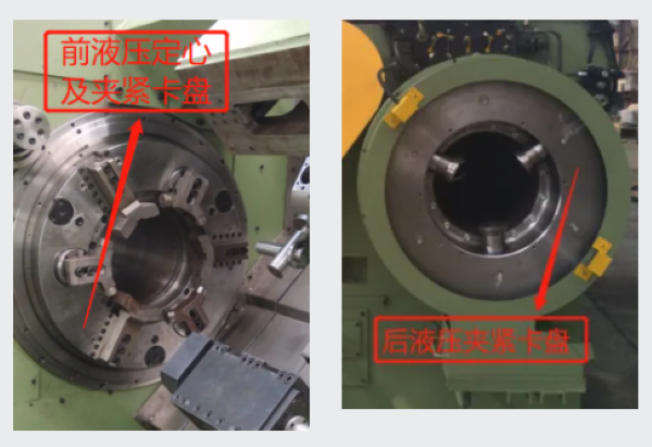
The front-and-rear clamping system uses dual hydraulic chucks to secure the steel pipe. Before final clamping, the front chuck activates a hydraulic motor that drives three centering jaws through a gear and multi-start screw mechanism. These jaws provide floating clamping and automatic centering, aligning the pipe with the spindle centerline. After centering, both chucks firmly grip the pipe. This dual-chuck design ensures stable two-point clamping, delivering excellent rotational stability and precision for high-quality threading operations.
06. Conformator System
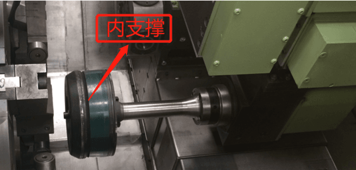
The Conformator features a rotating mandrel and hydraulic cylinder that controls a polyurethane stabilizer. Sized for different pipe diameters, it compresses against the inner wall and rotates with the pipe. This design reduces vibration, noise, and coolant leakage, while improving thread quality and preventing chips and fluid from entering the pipe interior during machining.
07. threading machine Turret System
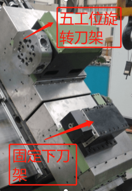
The CNC pipe threading machine features a high-performance Turret system for speed, power, and precision. The upper Turret uses a five- or six-station hydraulic or servo-driven design for fast indexing, firm locking, and accurate positioning, while the lower Turret remains fixed and robust. Both support Capto C6 tooling for stable cutting. With five feed axes driving the upper Turret (X1/Z1), lower Turret (Y1), and Channel-2 Turret (X2/Z2), three Turrets can operate simultaneously. This layout accelerates turning and threading, reducing cycle times and boosting throughput. Built for demanding environments, it ensures productivity and reliability for OCTG pipe processing.
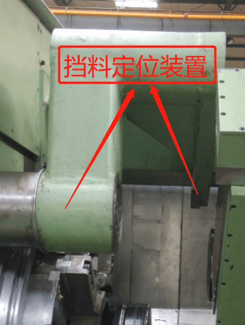
08. threading machine Pipe stopper device
The stop device, mounted at the front of the headstock, ensures precise positioning of the steel pipe inside the CNC pipe threading machine. It accurately stops the pipe at the required location, guaranteeing correct alignment before machining begins. If the pipe enters abnormally, the device absorbs impact energy, slows the pipe, and brings it safely to a halt. This protective function prevents equipment damage and ensures stable, reliable operation during high-volume pipe-processing tasks, delivering both safety and precision for demanding OCTG threading applications.
09. High‑Pressure Coolant System
The CNC pipe threading machine features a high-pressure, high-flow coolant system that delivers emulsion directly through the tool head and tool-bar channels. This design targets the cutting edge for rapid cooling, extended tool life, and superior thread quality. A chip conveyor with a return pump filters and recycles coolant, while a level-monitoring device ensures consistent and stable operation during high-volume machining.
10.Independent Hydraulic System
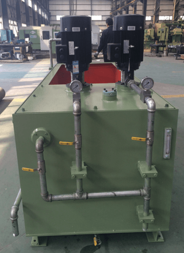
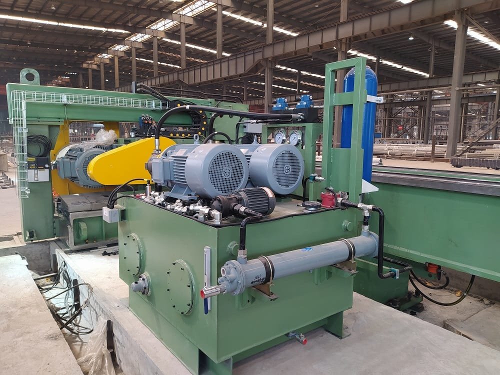
The CNC pipe threading lathe is equipped with an independent hydraulic pump station that powers all hydraulic functions of the machine and its loading platform. A valve block mounted on the headstock precisely controls chuck clamping, centering, the stop device, and Turret balancing for smooth operation. Integrated monitoring of oil level, pressure, and temperature ensures consistent performance and prevents system failures. This robust hydraulic system delivers reliability and stability, meeting the demanding requirements of OCTG pipe threading applications and supporting high-volume, precision machining environments.
11.Safety and Protection System
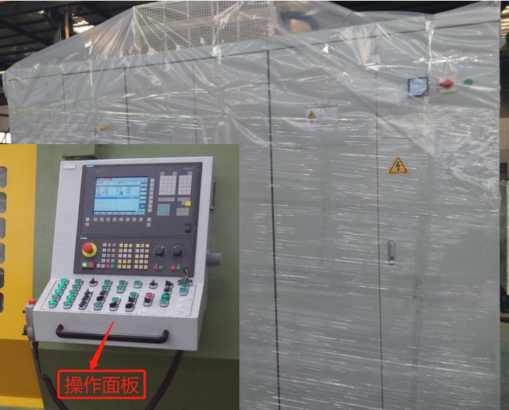
The CNC pipe threading machine offers multi-level safety protection across X, Y, and Z axes, including electrical, software, and mechanical limits to ensure safe, reliable operation. Stainless-steel telescopic covers fully enclose the bed and slideways, protecting guideways and ball screws from chips and coolant. A full sheet-metal enclosure prevents splashing and maintains a clean appearance. The front safety door features an interlock switch, while the electrical cabinet includes power-off protection when opened. All safety measures comply with CE standards, guaranteeing operator safety and stable performance for demanding OCTG pipe threading applications in continuous production environments.
12.Advanced Control System
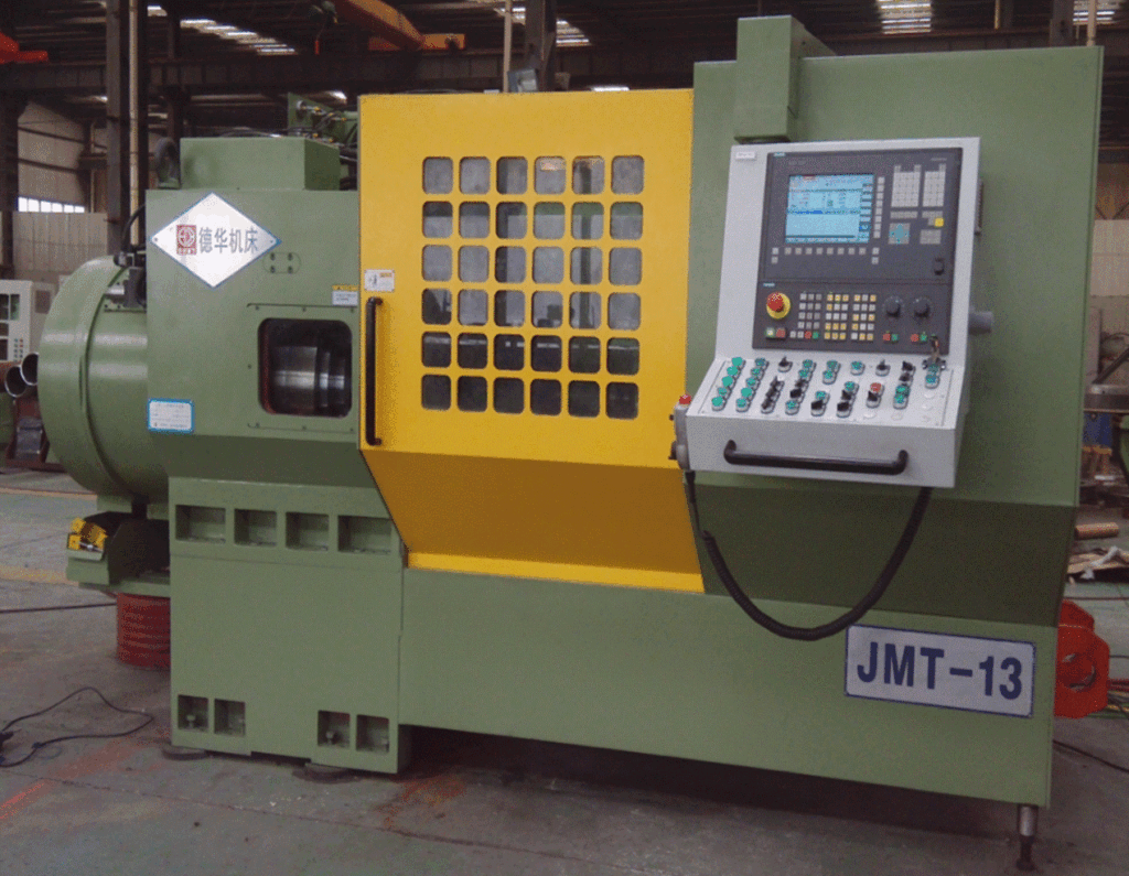
The CNC pipe threading machine is equipped with a SIEMENS or FANUC CNC system, offering automatic, semi-automatic, and manual control modes. The operator panel provides mode selection, real-time status display, and a touchscreen interface for entering key parameters such as pipe diameter, thread type, length, cutting speed, and feed rate. It also tracks pipe counts for production monitoring. The intuitive touchscreen simplifies programming, debugging, and maintenance, ensuring user-friendly operation. Whether used as a CNC pipe threading lathe or OCTG threading machine, this advanced control system delivers precise automation and flexible performance for high-efficiency pipe processing.
13.Auxiliary System
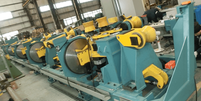
The auxiliary handling system serves as the loading and unloading platform for steel pipes. It is composed of a pipe pre‑alignment unit, a pipe conveying roller table, a rotating roller support, a step‑beam lifting and shifting mechanism, a roller and support‑roller adjustment unit, and a servo feeding device. Together, these components provide stable support during machining and ensure efficient material transfer, including feeding the pipe into the machine and removing it after processing.
Our Partner


Discover Our Full Range
