CNC Pipe Cutting Machine
The DSQG Series Pipe Cutting Machine represents a next-generation solution designed to meet the evolving demands of the global metallurgical industry. Engineered for precision and productivity, this advanced pipe cutting machine delivers energy-efficient, automated performance across diverse applications, including metallurgy, petrochemical processing, and mechanical manufacturing. Its innovative design ensures superior operational efficiency and reliability, setting a new benchmark for modern pipe cutting technology.
Unlike conventional pipe cutting setups, the DSQG Series introduces a breakthrough gear differential feed mechanism. This unique system enables the cutting tool to move longitudinally on a high-speed rotating cutter head while the pipe remains stationary.
By eliminating the need for rotating pipes, the machine significantly reduces energy consumption, minimizes vibration, and extends tool life. The result is cleaner pipe ends, enhanced cutting accuracy, and improved throughput, making it an ideal choice for high-performance industrial environments.
At the heart of the DSQG Series is a Siemens CNC or PLC control system that automates every stage of the cutting process. From pipe feeding and length setting to clamping, tool feeding, product discharge, and batch number printing for couplings, each operation runs seamlessly in a continuous cycle. This high level of automation not only boosts production efficiency but also supports large-scale manufacturing with minimal manual intervention, ensuring consistent quality and operational excellence.
Compared to traditional horizontal lathes and cutting saws, the DSQG Series delivers a substantial leap forward in design, functionality, and performance. Its modular structure and intelligent control system provide unmatched flexibility, allowing manufacturers to adapt quickly to changing production requirements. By integrating advanced automation and precision engineering, the DSQG Series helps companies modernize their operations and maintain a competitive edge in the global pipe cutting market.
In summary, the DSQG Series Pipe Cutting Machine is more than just an upgrade—it is a transformative solution for industries seeking efficiency, accuracy, and sustainability. With its innovative gear differential feed mechanism, automated control system, and energy-saving design, this machine sets a new standard for pipe cutting technology worldwide. For businesses aiming to optimize productivity and reduce operational costs, the DSQG Series is the ultimate choice.
Core Performance Advantages Features
The DSQG Series pipe cutting machine delivers high-speed, precision-driven cutting for industrial steel pipe applications. Designed by Hotstone Group, it integrates cutting-edge automation, structural reliability, and energy efficiency—making it a powerful solution for metallurgy, petrochemical, and mechanical manufacturing sectors.
01 .High-Efficiency &Excellent Cutting Performance
This pipe cutter adopts a globally advanced triple-blade simultaneous cutting system. All three tools operate in sync, significantly increasing cutting capacity and stability. Tool changes are quick and simple, which reduces downtime and supports high-throughput production environments.
02 .Low Operating Cost & Energy-Saving Design
Compared to traditional saw blades, the cutting inserts offer longer service life and lower cost per cut. Each blade handles more cycles, reducing replacement frequency. Moreover, the machine rotates the cutter head while keeping the pipe stationary. This design lowers power consumption, minimizes noise, and aligns with green manufacturing standards.
03 .Superior Cutting Accuracy innovation
The DSQG piping cutting machine produces clean, perpendicular cuts with minimal burr. As a result, it reduces the need for secondary processing and saves material. Unlike conventional saws that may cause 3–5 mm angular deviation, this system ensures consistent geometric precision—ideal for welding and assembly.
04 .Reliable Structure & Easy Maintenance
The spindle and feed mechanisms feature a compact, simplified design. All key components undergo heat treatment and precision grinding, ensuring long-term accuracy and stability. A hydraulic chuck provides strong clamping force, preventing pipe deformation and supporting continuous heavy-duty operation. Maintenance is straightforward, reducing downtime risk.
05 .Advanced Automation & User-Friendly Control
Equipped with Siemens 828D CNC or S7-1500 PLC, the system offers powerful logic control and intuitive human-machine interaction. Operators can easily switch between automatic, semi-automatic, and manual modes, adapting to various production needs.
06. Proprietary Technology with Full IP Ownership
we hold complete intellectual property rights for the machine’s core technologies, protected under national invention patents (Nos. 200810016217.6 and 200820022226.1). This ensures secure, long-term technical support and upgrade continuity.
07. Integrated Mechatronic System
The DSQG pipe cutting system combines mechanical, electrical, hydraulic, pneumatic, and control technologies into a unified platform. In addition to the main unit, it includes automated loading, feeding, positioning, clamping, product discharge, and stamping modules. Subsystems such as hydraulics, cooling, lubrication, and electrical control work together to enable precise, automated pipe cutting with continuous cycling.
08. High-Performance Spindle Unit
The spindle uses high-precision tapered roller bearings for excellent load capacity and smooth operation. Hydraulic oil provides cooling and lubrication for both bearings and gears, maintaining low thermal rise and high rigidity. An imported rotary seal at the spindle front prevents coolant ingress, extending service life
09. Precision Feed System
A servo motor directly drives the ball screw, paired with high-rigidity linear guides. This setup ensures fast response, low noise, and minimal backlash. The ball screw features an internal circulation design with preloaded floating spacers and is pre-stretched during assembly. These enhancements improve thermal stability and axial rigidity, ensuring high feed accuracy and repeatability.
10. Premium Component Configuration
All critical parts—including spindles, ball screws, bearings, hydraulic units, lubrication and cooling systems, drive belts, and electrical components—are sourced from trusted domestic and international brands. This guarantees long-term reliability, stable performance, and extended equipment lifespan.
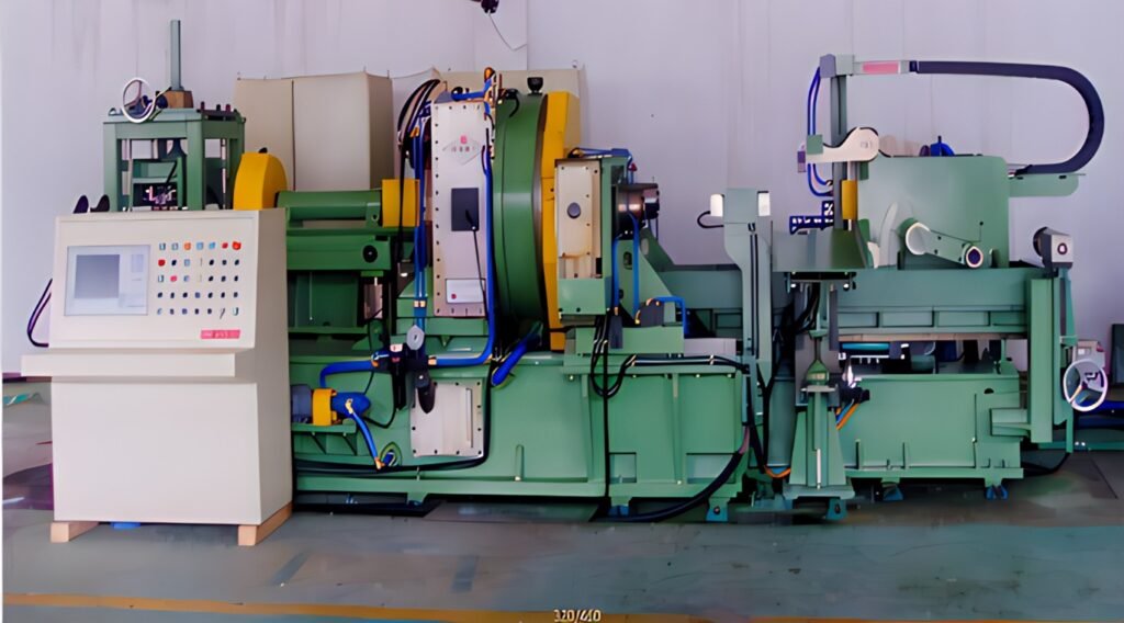
Tool Rotary pipe Cutting Machine Showcase
Specification of the Pipe Cutting Machine
| Item | Unit | DSQG-13 | DSQG-18 | DSQG-25 | DSQG-28 |
|---|---|---|---|---|---|
| Cutted Pipe Dia | Inch | 4 1/2 ”- 13 3/8 ” | 7 ”- 18 ” | 12 3/4 ”- 25 ” | 14 ”- 28” |
| Max Pipe Wall Thickness | mm | 32 | 40 | 50 | 60 |
| Max Process Pipe Length | mm | 6000-15000 | 6000-15000 | 6000-15000 | 6000-15000 |
| Spindle Speed Range | rpm | 50-400 | 40-320 | 35-150 | 30-140 |
| Feeding Stroke | mm | 50 | 75 | 90 | 100 |
| Main Motor Power | Kw | 37 | 45 | 55 | 55 |
| Cutting Accuracy | mm | 0.2 | 0.2 | 0.2 | 0.2 |
| Machining pipe ends and pipes Perpendicularity of the axis | mm | 0.15/100 | 0.15/100 | 0.15/100 | 0.15/100 |
| Machining surface roughness | um | Ra6.3 | Ra6.3 | Ra6.3 | Ra6.3 |
The Main Parts of the Pipe Cutting Machine
The main structural components of the machine tool adopt a robust steel welded structure. we applie advanced pre-welding treatment techniques, proven large-part welding procedures, standardized heat treatment, and high-precision machining processes. These integrated methods effectively eliminate residual welding stress while significantly enhancing the rigidity and load-bearing strength of the frame. As a result, the machine tool maintains long-term structural stability and performance under heavy-duty operating conditions.

Spindle Unit and Feed System Overview
The spindle box of the machine tool features a thick steel plate welded structure, reinforced with strategically placed internal ribs to ensure optimal rigidity. The spindle itself is made from high-strength alloy steel, undergoing heat treatment followed by precision grinding to achieve superior dimensional accuracy. Designed with a large through-hole configuration, the spindle is supported by imported high-precision tapered roller bearings. A hydraulic oil-based cooling and lubrication system maintains low thermal rise and high operational stability. As a result, the entire spindle assembly delivers excellent rigidity, thermal consistency, and high rotational accuracy—ideal for demanding cutting applications.
Gear Differential Feed & Servo-Controlled Cutting
The machine tool adopts a gear differential feed mechanism, enabling the cutting tool to feed longitudinally while mounted on a high-speed rotating cutter head. This design eliminates the need for workpiece rotation, effectively reducing machine vibration, extending tool life, and ensuring superior end-face roughness and perpendicularity—particularly critical for coupling production. The feed system utilizes a servo-driven mechanism, offering adjustable feed rates, high positioning repeatability, and stable motion control. Together, these features ensure the machine tool achieves both high cutting efficiency and consistent machining quality.
Clamping System

Rigid Hydraulic Chuck System: The rigid chuck utilizes a hydraulic cylinder to drive a pair of symmetrical swing arms via sliding blocks. This synchronized motion ensures uniform clamping force on both sides. The swing arms are mechanically linked to left and right sliders, which in turn actuate the rigid jaws to securely grip the steel pipe. Once clamping is complete, a locking cylinder engages to fix the sliders in position. This robust structure guarantees excellent pipe stability during high-speed cutting operations, minimizing vibration and ensuring precision.
Elastic Chuck System: The elastic chuck is actuated by four hydraulic cylinders controlled through a dedicated valve group. These cylinders connect to elastic jaws via a pull-plate mechanism, enabling flexible yet firm clamping of the pipe. The dual-chuck configuration further enhances stability during cutting, especially in long-pipe or high-precision applications. This system provides reliable holding force while accommodating slight pipe deformation, ensuring consistent cutting quality.
pipe Feeding Trolley and Positioning stopper

Servo-Driven Feeding Trolley (for Coupling Cutting Applications)
The feeding trolley system is powered by a high-precision servo motor, which drives the motion through a synchronous belt and ball screw assembly. To ensure smooth and accurate linear movement, the system incorporates high-rigidity linear guide rails. This configuration guarantees consistent feeding accuracy and operational stability during high-speed cutting cycles.
For secure material handling, the trolley features a hydraulic clamping mechanism actuated by a hydraulic cylinder. This structure firmly grips the steel pipe during feeding. To maintain synchronized motion between the dual clamping arms, a mechanical synchronization linkage is integrated between them. This ensures balanced clamping force and precise alignment, which are critical for maintaining cutting accuracy and minimizing material deviation.
Positioning Stopper
Mounted at the front end of the spindle box, the positioning stop plate serves as a mechanical reference point for precise pipe alignment during feeding. Its primary function is to ensure accurate axial positioning of the steel pipe before cutting begins, thereby enhancing dimensional consistency and machining precision.
In addition to its positioning role, the stop plate also acts as a protective buffer. In the event of a malfunction during pipe feeding—such as unexpected acceleration or misalignment—the stop plate absorbs impact energy from the incoming pipe. This built-in safety feature helps decelerate and halt the pipe smoothly, effectively protecting the machine tool from potential damage and maintaining operational safety.
Auxiliary equipment

The loading bench is composed of a pipe material stopper, a material taking device, a pinch roller and a specification adjusting device, etc. Its main function is to provide pipe material processing support and realize material transfer (that is, pipe material is sent into).
Lubricating System

The feed unit, rigid chuck, and servo feed mechanism utilize a centralized lubrication system. This system delivers oil to key lubrication points—such as linear guides, ball screw assemblies, and sliding surfaces—through an open-loop, total-loss configuration. Lubricating oil mixes with the coolant and is discharged after use. The electrical control system adjusts both the lubrication cycle and the oil volume at each point, ensuring optimal lubrication performance. A flow monitoring device is integrated and linked to the PLC, allowing real-time feedback to the operator regarding system status.
The spindle unit adopts a pressure-injection lubrication method. A motor-driven oil pump draws lubricant from the machine bed’s oil tank and delivers it to critical components such as bearings and gears within the spindle box. This forced lubrication system includes a filtration unit and an electronic flow switch to monitor oil flow at key points. The system promptly alerts the operator if any abnormality is detected.
The auxiliary engine bench employs a manual lubrication system to maintain effective lubrication at designated points. Additionally, the pipe cutting machine is equipped with a liquid level alarm to ensure timely replenishment and system reliability.
Emulsion Cooling System

The system integrates a high-pressure, high-flow emulsion cooling unit. Through internal coolant channels in the threading machine’s tool head and tool rod, cutting fluid is directly sprayed onto the cutting edge and machining zone. This setup rapidly cools both the tool and the workpiece, significantly extending tool life and enhancing machining quality. It ensures strong, targeted cooling during cutting operations while facilitating efficient chip evacuation to maintain surface integrity.
To support continuous operation, the system includes a chip extractor and a return pump. These components filter the emulsion and cycle it from the chip collection tank back to the cooling reservoir. A liquid level detection device is also installed to monitor coolant volume and ensure stable system performance.
hydraulic system

The hydraulic pump station operates as a fully independent unit, allowing flexible installation based on end-user requirements. It governs all hydraulic functions of the machine’s main engine and the loading platform.
A dedicated hydraulic valve stand, mounted on the headstock, integrates all solenoid valves, pressure-reducing valves, and other hydraulic actuators. These components precisely control the clamping and centering of the hydraulic chuck jaws, the positioning stopper, and the balance of both the feed slide and the tool holder.
Control System

The equipment integrates a SIEMENS numerical control system or PLC to support automatic, semi-automatic, and manual operation modes. This enables fully automated pipe processing with high precision and flexibility.
The operator panel includes mode selection switches for manual, semi-automatic, and automatic control, along with real-time status displays of machine operations. A user-friendly touch screen allows direct input of processing parameters such as pipe diameter, hook type, pipe length, cutting speed, and feed rate. The system also features an automatic tube counting function.
Designed for intuitive human-machine interaction, the interface simplifies programming, debugging, and maintenance—ensuring efficient operation and ease of use.
Our Partner

