Billet Cutting
Saw Machine JBS-850

Our Story

CNC Billet Cutting Saw -JBS-850
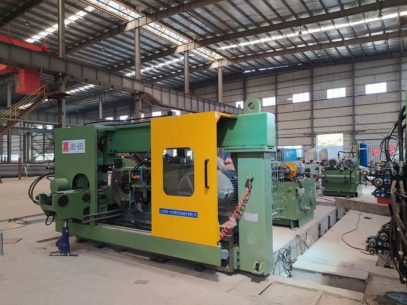
The equipment is a circular cold saw featuring horizontal cutting and carbide saw blades, with a machine body made of concrete structure to absorb vibration and exhibit excellent deformation resistance. Dual horizontal guide rails ensure stable sawing processes, while hydraulic damping reduces vibrations during cutting. The inlet and outlet fixtures are automatically separated to prevent collisions between the workpiece and the saw blade. Additionally, the equipment comes equipped with a SIEMENS PLC control system for simple parameter input and fast start-up times. Finally, chips are discharged through a chain-type conveyor belt.

Our Story

The Advantage of the Billet Cutting Saw

The sawing transmission box features a large and small gear anti-backlash structure. The saw blade transmission flange is splined with the main shaft. The clamping device adopts a vertical clamping method, consisting of a fixed clamp and a floating clamp. The upper jaw is driven by a hydraulic cylinder, while the lower jaw of the fixed clamp has a fixed V-shaped design, and the lower jaw of the floating clamp is controlled by two separate hydraulic cylinders. The feed system is powered by an AC servo motor and ball screw mechanism. The electrical control includes automatic mode, semi-automatic mode, and manual mode. Additionally, the saw possesses storage capabilities for all necessary pipe information (such as blank diameter, current, and sawing parameters), allowing for easy viewing and archiving.

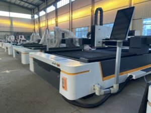
cutting saw /cutting saw for billet on the site

Composition of the Billet Cutting Machine

The billet cuting saw machine mainly consists of the following Parts

Cut Saw Machine

The main machine is composed of the following parts: saw tool box (including pulley), main transmission device, slide feed device, bed base, etc

Hydraulic System

The hydraulic station for the sawing machine consists of a motor, hydraulic pump, heater, water cooling and oil level indicating device, oil tank, valve stand, etc., equipped with functions such as oil temperature control, oil level monitoring and pressure alarm. The designed operating range for the hydraulic system is between +5°C to +45°C while utilizing a water cooling system to maintain the hydraulic oil temperature within 0°C to 35°C.

Air Cooling System

The main function of the air cooling system is to cool the saw blade and the cutting area. It is composed of pipe cooler, nozzle, pipe, etc.
The air is cooled through the pipeline cooler to reduce the temperature of the teeth and disk body, improve the service life of the saw blade and reduce the equipment load.

Centralized lubricating system

The central lubrication system is mainly used for intermittent and accurate oil dose lubrication of lubricating points such as guide rail, ball screw and nut pair. The nominal pressure of the lubrication pump is usually 2Mpa, the power is 0.02Kw, the flow rate is 0.15L/min, and the tank capacity is 4L

Control System

The Billet saw and table control system is operated by Siemens’ cutting-edge S7-1500 control system, which is integrated with Siemens’ state-of-the-art drive system and feed servo motor. It features a 10.4-inch touch screen with vibrant colors and high resolution, providing an advanced man-machine interface.

Auxiliary Equipment

The auxiliary equipment mainly consists of a magnetic sawdust chain, a measuring mechanism with a feeding trolley, and a saw blade changing device consisting of a cantilever hoist and an electric hoist

Specification Of JBS -850 Billet Cutting Saw

Items Unit Specifications Remarks
Performance
Processed Billet Dia Range mmΦ150mm 、 Φ180mm 、 Φ200mm
Max Process Billet Lengthmm 12000
Max Measuring Fixed Lengthmm -4500
Spindle
Spindle Rotating Patterncontinuous variable transmission
Overall Ratio29.859
Spindle Motor Powerkw 55
Saw Blade Diamm 830
Pressure Plate Flange Diamm 340
Feeding (X)
X Axis Travelmm 320
X Axis Ball Screw (Dia x Lead)mm 63×10
X Axis Servo Motorkw 1Fk7108 8kw
Fast Surface Speedmm/min 6000
Clamping System
Drive PatternHydraulic
Vertical jaw travelmm 320
Horizontal jaw travelmm 50
Clamping ForceKN35-55 KN (2 sets)
Travel between feeding and discharging Clamp Fitsmm5
Hydraulic System
Servo Motor PowerKw 22
Hydraulic Pump Flow L/min105
Working PressureBar 120
Oil Tank CapacityL600
Centralized Lubricating System
SizeAMO-II-150S
Motorw20w 220v/50HZ
Hydraulic Pump FlowL/ Min0.15
Working PressureBar20
Oil Tank CapacityL4
Air Cooling System
Air FlowNM3/h300
Working PressureBar5-6 Bar
Chain Chip Conveyer System
Distance between the chip outlet and the groundmm1000
Conveying Speedm/min 2.5
MotorKw0.55kw 380 v 50 Hz
Control System
NC SystemSimens Simatic S7-1500
HMITouch Screen 10.4 Inch
Note : The Specificaion on the standard basis , for steel bar cutting , if any detailed requirements , just let us know , we will send you back all the details the first tim

Mechanical Introduction of the Billet Cutting Saw
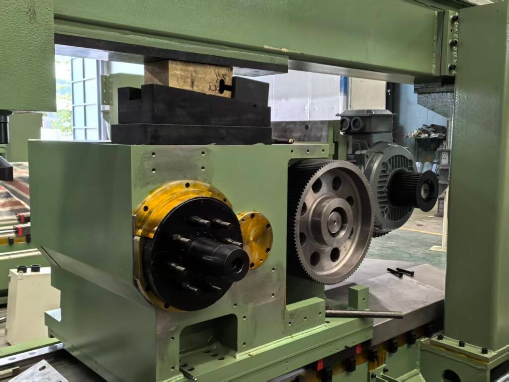
(1) The Saw Tooling Box of the cutting saw

The saw box is fabricated using Q345-B material and undergoes aging treatment to eliminate internal stress. The four-row bearing hole processing technology is optimized, and the combined boring bar ensures precise hole positioning and dimensional accuracy when closing the box with the cover. The gear features a no-backlash transmission structure, made of high-quality steel that has been quenched and ground to achieve level 6 accuracy. The input/output shafts and intermediate shafts are manufactured from high-quality hardened steel. Precision bearings are used in the saw box, with INA needle roller bearings selected for specific applications and NSK or FAG products chosen for other bearings. The belt groove position remains fixed, while an unloading structure at the I-axis prevents bending or deformation, facilitating convenient loading/unloading operations as well as ensuring connection with the main motor. Oil cooling lubrication is employed for both the main shaft and gear to maintain good rigidity, low temperature rise, and high precision within the entire rotating system. Furthermore, incorporating a no-backlash transmission structure inside the saw box reduces impact on teeth and support components, thereby enhancing service life while minimizing noise levels.

(2) The guide mechanism of the cutting saw

The guiding mechanism is composed of a drag plate, a pair of pre-tightened roller linear guide rail and an additional pressure unit. The pressure unit includes an oil cylinder, a wedge-shaped block and a guide rail. When the gear box fast forward into the working time, the cylinder pushes the block to fix the flat guide rail tightly, so as to effectively transfer the cutting force acting on the saw blade to the frame, reduce the tipping moment generated on the main rail, and improve the working life of the guide mechanism; During non-cutting working hours, the cylinder rod is withdrawn to reduce the load on the feed mechanism. The additional slide rail is at the same level as the lowest position, and can accommodate the largest diameter of the saw blade, on this basis, better transfer the cutting force to the frame to protect the guide rail

(3) The Main Transmission System of the cutting saw

The machine is equipped with a powerful variable frequency motor. The spindle motor drives the spindle and saw blade to turn at high speed by belt and gear

(4)Slide feed device

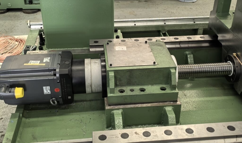
The servo motor is slowed down by the precision reducer and connected with the ball screw to drive the saw box to move forward and backward along the guide rail of the bed.

(5) The Machine Base

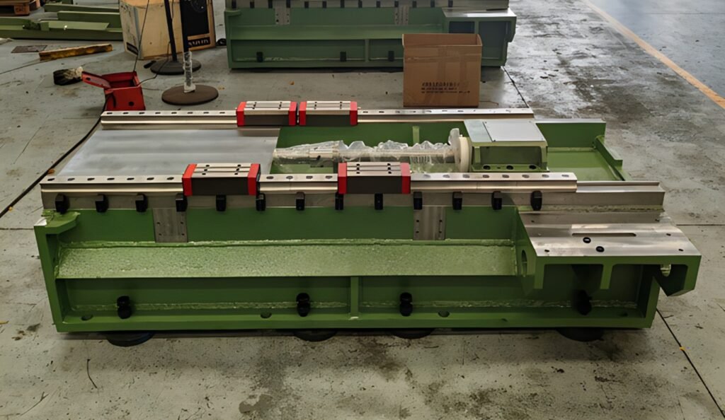
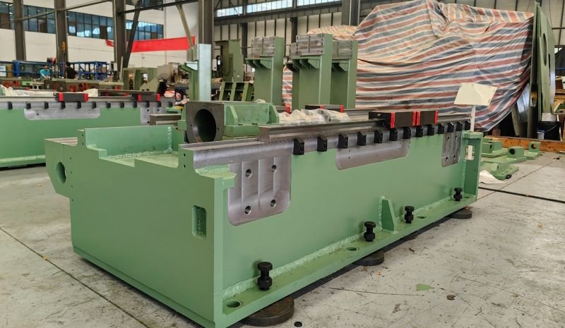
The bed base is the base component of the machine and is of thick plate welded construction and filled with concrete to increase rigidity. After aging treatment, it has high stability and is not easy to deform. The bed is equipped with two rolling guides to guide the movement of the saw box, thus providing good stability.

(6) The Saw blade guide/shock absorber

The machine is equipped with three sets of guiding/damping devices, which are installed on both sides of the saw blade to ensure that there is no vibration when the blade enters and exits during sawing, and to prevent bending vibration during high-speed rotation. The friction plate is used as the liner.

(7) The Clamping Device

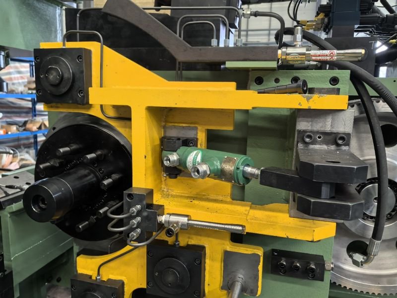
Each saw blade is equipped with a set of clamps on both sides, including horizontal and vertical clamps and a clamp base for fastening the tube billet. These clamps are hydraulically fastened and also have an automatic separation function for quick exit of the saw blade, with a separation distance of 5mm.

(8) The Lift roller table at exit

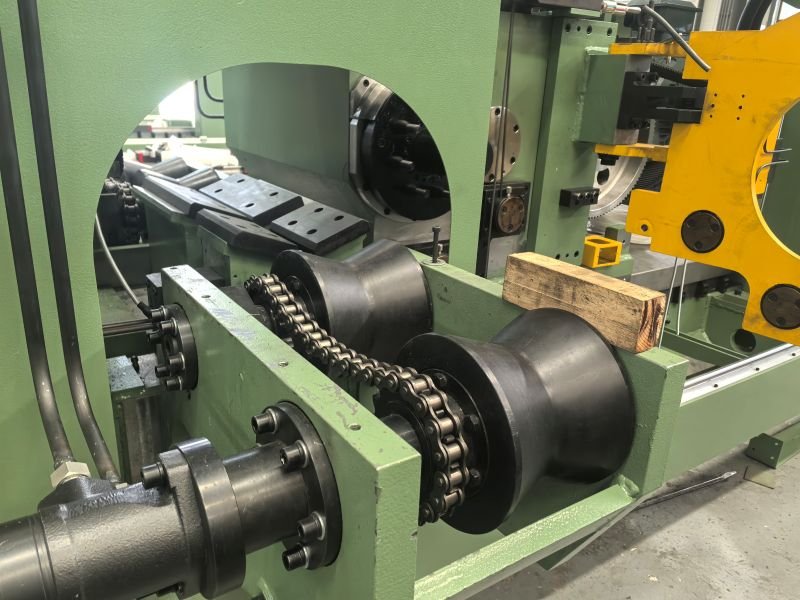
At the discharge position near the edge of the saw, an adjustable height lifting roll of 140°V is provided and hydraulically controlled to ensure that the tube billet can pass through the clamping device without colliding with it.

(9) The Chip cleaning device

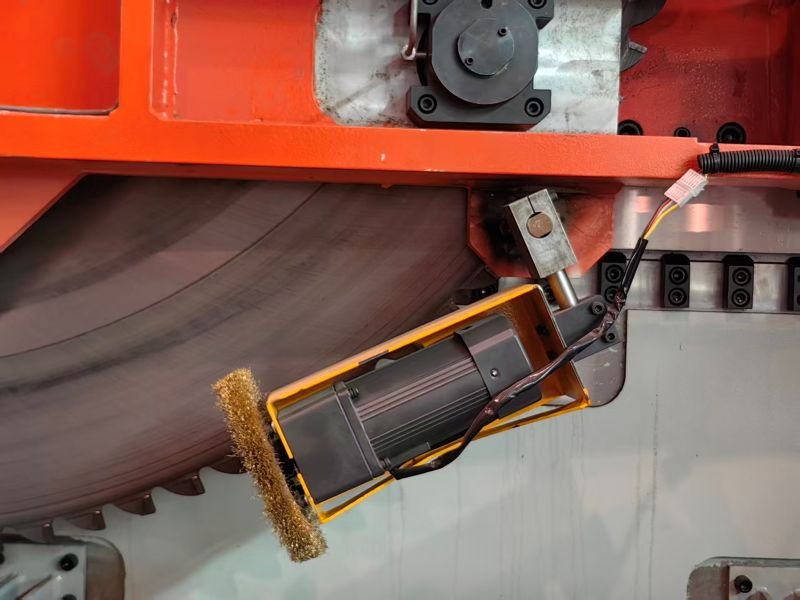
A micro-motor drives a brush to clean the sawtooth surface.

(10) The Chip Conveyor Chain (optional )

The chip is discharged from the sawing area through the magnetic structure

(11) The Fixed Measuring Device (optional)

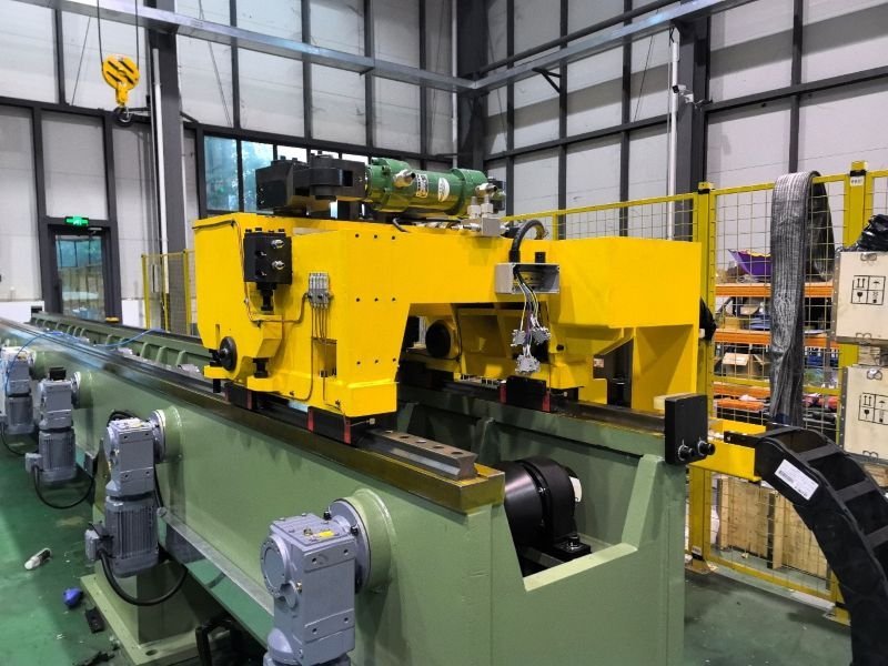
The feeding trolley is installed on the base, and is driven by the servo reduction motor through the rack and pinion to move forward and backward on the base rail. The billet is clamped by the hydraulic clamping arm of the feeding trolley,In order to avoid the collision between the billet and the fixture when the car is fed, the base has the lifting function

(12) The Saw blade replacement device (Optional )

The saw blade replacement is placed next to the saw machine and consists of a cantilever hoist and electric hoist.

Stay Connected with Us

Let’s Create Together

Connect with us to explore how we can make your vision a reality. Join us in shaping the future.